目的
在改裝 3D 印表機時,需要在有限的空間內加上一些調整時會用的裝置,只要把它安裝在可動的座上。參考網路的作法,使用舵機 MG90S 來改變位置。MG90S 是使用 50Hz 的方波的 duty cycle 寬度來控制舵的角度。
為了瞭解 MG90S 的運作方式,使用 STM32F103 的開發板來控制它,程式語言則是使用 Forth。Forth 兼具 interactive 和 compile 的特性,可以在 terminal 直接發送指令,也可將一堆指令包成一個 word (等同於其他程式言的 function),然後在 terminal 直接測試新的 word。並且有能夠直接存取特定 IO 的低階指令,在開發硬體上很方便。
參考
- STM32 PWM Example – Timer PWM Mode Tutorial
- STM32 Servo Motor Control With PWM – Servo Library Example Code
- Getting Started with STM32F103: Delay using timer
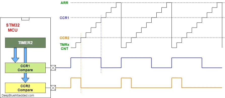
STM32 的 PWM 原理
STM32 有不同編號的 MCU,功能上差不多,但控制上稍微不同,必須找對應的 Reference manual 來看,如 STM32F101xx 要看 RM0008 的文件,STM32F407/417 則要看 RM0090 的文件。
一張圖勝於長篇解說,下面的圖借自網站 deepbluembedded 的圖。
STM32F103 微控制器采用 Cortex-M3 内核,CPU 最高速度达 72 MHz。MG90S 控制信號的頻率為 50Hz。
以下參考 embeddedexpert 的關於 timer 使用的說明。
1. stm32 的 timer 的工作簡要說明:
A Timer Module in its most basic form is a digital logic circuit that counts up every clock cycle. More functionalities are implemented in hardware to support the timer module so it can count up or down. It can have a Prescaler to divide the input clock frequency by a selectable value. It can also have circuitry for input capture, PWM signal generation, and much more as we’ll see in this tutorial.
Let’s consider a basic 16-Bit timer like the one shown below. As a 16-Bit time, it can count from 0 up to 65535. Every clock cycle, the value of the timer is incremented by 1. And as you can see, the Fsys is not the frequency that is incrementing the timer module. But it gets divided by the Prescaler, then it gets fed to the timer.

Basically, in timer mode, the TCNT register is incremented by 1 each clock cycle @ the following frequency (Fsys/PSC). This means if the Fsys is 80MHz & PSC is 1:1024, the TCNT gets incremented by 1 every 12.8μSec. Therefore, if you start this timer to count from 0 until it reaches overflow (at 65535), a flag will be set and starts over from zero.
2. 設定延遲時間:
Since STM32F103 has multiple timers, we shall use timer2 for this guide.
First, we need to enable clock access to TIM2 of STM32F1. In order to find which bus is connected to, we need the block diagram of STM32F103 which can be found in datasheet of STM32F1.
From the block diagram, we can find that TIM2 is connected to APB1 bus:

/*Enable clock access to timer2*/
RCC->APB1ENR|=RCC_APB1ENR_TIM2EN;
Now, we can create a function named delay which takes ms as argument to indicate the amount to be delayed as following:
void delay(uint16_t ms)Within the function, set the prescaller for the timer, since STM32F103C8 by default runs at 8MHz, we shall use prescaller of 8000-1 as following:
TIM2->PSC=8000-1; //8 000 000 Hz / 8 000 = 1 000 Hz (1 ms) Set the Auto reload register the desired delay -1 :
TIM2->ARR=ms-1; // desired delayEnable the timer from control register 1 (CR1):

TIM2->CR1|=TIM_CR1_CEN; Wait until the update flag is set in status register and then clear it once it is set:

while(!(TIM2->SR&TIM_SR_UIF)){} //wait UIF to be set
TIM2->SR&=~TIM_SR_UIF; //reset UIF
Finally, disable the timer:
TIM2->CR1&=~TIM_CR1_CEN;3. 全部的程式碼:
Hence, the entire code as following::
#include "stm32f1xx.h"

void delay(uint16_t ms)
{
	TIM2->PSC=8000-1; //8 000 000 Hz / 8 000 = 1 000 Hz (1 ms)
	TIM2->ARR=ms-1;   // desired delay
	TIM2->CR1|=TIM_CR1_CEN;
	while(!(TIM2->SR&TIM_SR_UIF)){} //wait UIF to be set
	TIM2->SR&=~TIM_SR_UIF; //reset UIF
	TIM2->CR1&=~TIM_CR1_CEN; // Disable the timer
}

int main(void)
{
	/*Enable clock access to GPIOA*/
	RCC->APB2ENR|=RCC_APB2ENR_IOPAEN;

	/*Configure PA0 as output*/
	GPIOA->CRL|=GPIO_CRL_MODE0;
	GPIOA->CRL&=~(GPIO_CRL_CNF0);

	/*Enable clock access to timer2*/
	RCC->APB1ENR|=RCC_APB1ENR_TIM2EN;

	while(1)
	{

		GPIOA->BSRR=GPIO_BSRR_BS0;//Set PA0 to high
		delay(1000); //Delay for 1 seconds
		GPIOA->BSRR=GPIO_BSRR_BR0; // Set PA0 to low
		delay(1000); // Delay for 1 seconds

	}
}
Forth 程式
依據上面的說明,以及參考其他的 Forth 程式,撰寫的 PWM 測試程式如下
\ STM32f103 PWM functiontest
\ 由 GPIO 可用的 alternate function 決定使用的 timer 和 channel
\ PA1 -- USART2_RTS / ADC12_IN1 / TIM2_CH2

\ 8000000 constant HCLK
72 1000 1000 * *  constant HCLK  \ 72 MHz ?
\ 80 1000 1000 * *  constant HCLK

$40021000 constant RCC_BASE
  RCC_BASE $18 + constant RCC_APB2ENR
  RCC_BASE $1C + constant RCC_APB1ENR

4 constant GPIOAEN
1 constant TIM2EN

$40010800 constant GPIOA
    GPIOA $0 + constant GPIOA_CRL
    GPIOA $4 + constant GPIOA_CRH
    GPIOA $8 + constant GPIOA_IDR
    GPIOA $C + constant GPIOA_ODR
    GPIOA $10 + constant GPIOA_BSRR
    GPIOA $14 + constant GPIOA_BRR
    GPIOA $18 + constant GPIOA_LCKR

$40000000 constant TIM2 ( Advanced timer )
TIM2 $0 + constant TIM2_CR1 ( read-write )  \ control register 1
TIM2 $4 + constant TIM2_CR2 ( read-write )  \ control register 2
TIM2 $8 + constant TIM2_SMCR ( read-write )  \ slave mode control register
TIM2 $C + constant TIM2_DIER ( read-write )  \ DMA/Interrupt enable register
TIM2 $10 + constant TIM2_SR ( read-write )  \ status register
TIM2 $14 + constant TIM2_EGR ( write-only )  \ event generation register
TIM2 $18 + constant TIM2_CCMR1 ( read-write )  \ capture/compare mode register output  mode
TIM2 $1C + constant TIM2_CCMR2 ( read-write )  \ capture/compare mode register output  mode
TIM2 $20 + constant TIM2_CCER ( read-write )  \ capture/compare enable  register
TIM2 $24 + constant TIM2_CNT ( read-write )  \ counter
TIM2 $28 + constant TIM2_PSC ( read-write )  \ prescaler
TIM2 $2C + constant TIM2_ARR ( read-write )   \ auto-reload register
TIM2 $34 + constant TIM2_CCR1 ( read-write )  \ capture/compare register 1
TIM2 $38 + constant TIM2_CCR2 ( read-write )  \ capture/compare register 2
TIM2 $3C + constant TIM2_CCR3 ( read-write )  \ capture/compare register 3
TIM2 $40 + constant TIM2_CCR4 ( read-write )  \ capture/compare register 4
TIM2 $48 + constant TIM2_DCR ( read-write )  \ DMA control register
TIM2 $4C + constant TIM2_DMAR ( read-write )  \ DMA address for full transfer
TIM2 $30 + constant TIM2_RCR ( read-write )  \ repetition counter register
TIM2 $44 + constant TIM2_BDTR ( read-write )  \ break and dead-time register

1 7 lshift constant ARPE 			\ Auto-reload preload enable
1 constant CEN								\ Counter enable
1 3 lshift constant OPM	 			\ One-pulse mode
1 constant UG		              \ Update generation

\ GPIOA_CRL - only for PA0 - PA7
: gpioa-mode! ( mode pin# -- )
  4 * dup
  $F swap lshift not GPIOA_CRL @ and
  -rot lshift or GPIOA_CRL !
;

: set-pwm ( period dutycyle -- )
	1- TIM2_CCR2 !	  \ duty cycle
	1- TIM2_ARR !	  \ period
;

: s-psc
  1- TIM2_PSC !
;

: p-psc
  TIM2_PSC @ 1+ .
;

: s-arr
	1- TIM2_ARR !	  \ period
;

: p-arr
	TIM2_ARR @ 1+ .	  \ period
;

: s-ccr
  1- TIM2_CCR2 !
;

: p-ccr
   TIM2_CCR2 @ 1+ .
;

\  --- init output PA1
: init-PA1 ( -- )
  \ IO port A clock enabled
  GPIOAEN RCC_APB2ENR bis!

  \ PA1 -> mode: alternate -> set value 1010
  \ CNF  - 10 -> 1: Alternate Function, output, 0: Push-pull
  \ MODE - 10: Maximum output speed 2 MHz
  %1010 1 gpioa-mode!
;

  \ 110: PWM mode 1 - In upcounting, channel 1 is active as long as TIMx_CNT<TIMx_CCR1
  \ else inactive. In downcounting, channel 1 is inactive (OC1REF=‘0) as long as
  \ TIMx_CNT>TIMx_CCR1 else active (OC1REF=1).

\ --- init TIM2_CH2
: init-tim2_ch2 ( -- )
	TIM2EN RCC_APB1ENR bis!			\ TIM2 clock enabled
	ARPE TIM2_CR1 ! 			\ ch2 Auto-reload preload enable

  \ Bit 5 CC2P: Capture/Compare 2 output polarity, 0: OC2 active high.
  \ Bit 4 CC2E: Capture/Compare 2 output enable
	1 4 lshift TIM2_CCER ! 				\ CC2E -> OC2 signal is output on the corresponding output pin
	1 11 lshift TIM2_CCMR1 bis!			\ OC2PE (bit 11) -> Output compare 2 preload enable

	%110 12 lshift TIM2_CCMR1 bis!	\ Output compare 2 mode -> 110: PWM mode 1

  \ Update generation - Reinitialize the counter and generates an update of the registers.
	UG  TIM2_EGR !
;

: pwm-init ( -- )
  init-PA1
  init-tim2_ch2

  \ HCLK 是 72MHz,prescaler 不能超過 65536
  \ 所以只能設到 2KHz
  HCLK 2000 / 1- TIM2_PSC !		\ prescaler -> 2000 Hz = 0.5 ms
  2000 50 set-pwm			\ 1000ms - 50ms period - dutycycle as initial value

  \ counter enable
	CEN TIM2_CR1 bis!
;
舵機控制
MG90S - (S: 金屬齒輪),模拟舵机,180度 - 才能控制角度,360 度只能旋轉
数字舵机Digital Servo和模拟舵机Analog Servo
PWM 測試
控制信號頻率 50Hz,週期 20ms
8MHz = 8*1000*1000
prescaler: 1000 => 8*1000
prescaler for 1us => 1MHz
-----------
舵機是一種位置(角度)伺服的驅動器,適用於那些需要角度不斷變化並可以保持的控制系統。目前在高檔遙控玩具,如航模,包括飛機模型,潛艇模型;遙控機器人中已經使用得比較普遍。舵機是一種俗稱,其實是一種伺服馬達。
其工作原理是:
控制信號由接收機的通道進入信號調製晶片,獲得直流偏置電壓。它內部有一個基準電路,產生週期為20ms,寬度為1.5ms的基準信號,將獲得的直流偏置電壓與電位器的電壓比較,獲得電壓差輸出。最後,電壓差的正負輸出到電機驅動晶片決定電機的正反轉。當電機轉速一定時,通過級聯減速齒輪帶動電位器旋轉,使得電壓差為0,電機停止轉動。當然我們可以不用去瞭解它的具體工作原理,知道它的控制原理就夠了。就象我們使用電晶體一樣,知道可以拿它來做開關管或放大管就行了,至於管內的電子具體怎麼流動是可以完全不用去考慮的。
舵機的控制:
舵機的控制一般需要一個20ms左右的時基脈衝,該脈衝的高電平部分一般為0.5ms~2.5ms範圍內的角度控制脈衝部分。以180度角度伺服為例,那麼對應的控制關係是這樣的:
0.5ms--------------0度;
1.0ms------------45度;
1.5ms------------90度;
2.0ms-----------135度;
2.5ms-----------180度;
這只是一種參考數值,具體的參數,請參見舵機的技術參數。
小型舵機的工作電壓一般為4.8V或6V,轉速也不是很快,一般為0.22/60度或0.18/60度,所以假如你更改角度控制脈衝的寬度太快時,舵機可能反應不過來。如果需要更快速的反應,就需要更高的轉速了。
要精確的控制舵機,其實沒有那麼容易,很多舵機的位置等級有1024個,那麼,如果舵機的有效角度範圍為180度的話,其控制的角度精度是可以達到180/1024度約0.18度了,從時間上看其實要求的脈寬控制精度為2000/1024us約2us。如果你拿了個舵機,連控制精度為1度都達不到的話,而且還看到舵機在發抖。在這種情況下,只要舵機的電壓沒有抖動,那抖動的就是你的控制脈衝了。而這個脈衝為什麼會抖動呢?當然和你選用的脈衝發生器有關了。
------------
0.5ms - 0 度
14.7ms - 90度
24.5ms - 180度
stm32f103
較佳的設定
psc - 7200 --> 10KHz -- 0.1ms
arr - 2000 -> 0.1ms * 200 = 20ms -> 50Hz
0.1ms * 500 = 50ms
0.5ms -- -90度
150 -- 0度
crr = 250 -- 90度
hclk = 72000000
hclk 100000 / s-psc => 100k -- 10us
20ms = 10us*100 *20
0.5ms = 500us = 10us * 50
150ms = 10us * 100*150
1Hz - 100us*10*1000
使用這個設定
2000 s-arr => 20ms -> 50Hz
50 s-ccr ok. (0 度)
150 s-ccr ok. (90 度)
250 s-ccr ok. (180 度)